
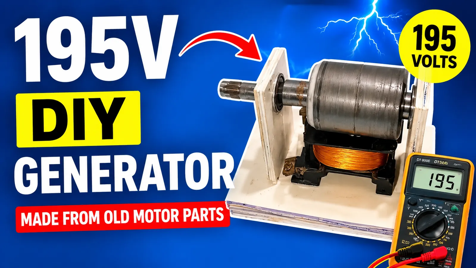
Understanding the DIY Electricity Generator and How It Works
A DIY electricity generator is an educational example of how mechanical energy can be converted into electrical energy through electromagnetic induction. In the project described in this experiment, an old BLDC motor rotor containing permanent magnets is reused together with a copper coil, PVC support structure, bearings, connecting wires, and a voltmeter to demonstrate basic electricity generation. The fundamental principle behind an electrical generator is relatively simple: when a magnetic field moves relative to a conductive coil, the changing magnetic flux can induce an electrical voltage in the conductor. This principle, known as electromagnetic induction, is the foundation of many commercial electric generators, alternators, motors used as generators, and renewable energy systems. In this particular experiment, the permanent magnets mounted on the reused motor rotor provide the moving magnetic field, while the copper coil acts as the electrical conductor in which voltage is induced as the rotor spins. The experiment is therefore useful for understanding energy conversion, because
the input energy does not come from the generator itself; instead, mechanical energy must be supplied by rotating the rotor. When the rotor is manually turned with a rope, the magnets move past the coil and the magnetic field changes around the coil. This changing magnetic environment produces an electrical potential that can be observed with a voltmeter. The reported test reaches approximately 195 volts under the particular experimental conditions, but this number should not be interpreted as a fixed or guaranteed power output. Generator voltage depends on several factors, including rotor speed, magnet strength, coil design, number of turns, wire characteristics, magnetic-gap distance, electrical load, and the overall construction of the generator. A voltmeter reading of approximately 195 volts also does not automatically mean that the generator can deliver 195 volts continuously to household appliances or provide useful backup power. Voltage and electrical power are different measurements: voltage describes electrical potential difference, while power depends on both voltage and current. For example, a generator could potentially show a high voltage on a meter while being unable to supply significant current to a practical load. This distinction is extremely important when discussing electric generator efficiency, power generation, and real-world electrical systems. The experiment also demonstrates why repurposing old electrical components can be valuable for learning. Instead of discarding an old BLDC motor, its rotor and permanent magnets can be studied as components of a simple generator system. The PVC frame provides mechanical support, while bearing holders help keep the rotor aligned and allow it to rotate with reduced friction. The copper coil provides the electrical path where induced voltage can be measured. When the rotor speed increases, the rate at which the magnetic field changes around the coil also increases, which can result in a higher measured voltage. When the rotor slows down, the induced voltage generally decreases. This relationship explains why manually spinning a generator may produce a changing meter reading rather than a perfectly stable output. The light-bulb test provides another practical demonstration because connecting an electrical load changes the operating conditions of the generator. A bulb may glow when sufficient voltage and current are available, but the brightness can vary with rotor speed and generator design. From an educational perspective, this project introduces several important concepts used in electrical engineering, including electromagnetic induction, permanent magnets, copper windings, mechanical rotation, voltage measurement, electrical loads, and energy conversion. It also demonstrates an important principle that applies to large commercial generators: electricity must be produced by supplying energy to the generator through some mechanical or other primary energy source. In a hydroelectric power plant, flowing water supplies the mechanical energy; in a wind turbine, moving air rotates the turbine; in a conventional generator system, an engine supplies mechanical rotation; and in a laboratory experiment such as this one, the operator supplies mechanical energy by rotating the shaft. Therefore, the project should be viewed as a practical demonstration of electricity generation technology, rather than a source of free or unlimited energy. Understanding this distinction helps viewers evaluate generator claims realistically and recognize why generator performance must always be measured under defined conditions, including rotational speed, voltage, current, electrical load, and operating time. Most importantly, the approximately 195-volt reading shown in the experiment demonstrates that an electrical potential can be produced from the rotating magnetic system, but safe and reliable use requires proper electrical engineering practices, appropriate insulation, suitable measurement equipment, and a clear understanding of the difference between open-circuit voltage and usable electrical power.
Reusing an Old BLDC Motor Rotor for Electricity Generation
One of the most interesting parts of this DIY electricity generator experiment is the decision to reuse an old BLDC motor rotor instead of manufacturing a completely new magnetic assembly. BLDC, or brushless DC, motors are widely used in applications such as electric bicycles, cooling systems, industrial equipment, robotics, pumps, and other electrically driven machines because they use permanent magnets and electronic commutation rather than traditional mechanical brushes. When an old BLDC motor is opened, its internal construction can reveal useful components that may be repurposed for an educational electric generator project. In this experiment, the outer housing is carefully opened and the rotor is removed so that its permanent magnets can be examined and reused. The rotor is particularly important because the permanent magnets provide the magnetic field required for electromagnetic induction. A generator does not create electrical energy simply because magnets are present; mechanical energy must move the magnetic field relative to the copper winding. As the rotor rotates, its permanent magnets pass the stationary coil, causing the magnetic flux through the coil to continuously change. This changing magnetic flux induces an electrical voltage in the copper conductor. The concept is closely related to the operating principles found in commercial alternators and permanent-magnet generators. Reusing an existing rotor can also make an experimental project more accessible because the magnets are already positioned as part of a balanced rotating assembly. However, the condition of the rotor should be inspected carefully before it is used. The magnets should be securely attached, the rotor should not have excessive physical damage, and the shaft or rotating surface should be capable of operating without dangerous wobbling. Mechanical balance is particularly important because even a small imbalance can produce vibration as rotational speed increases. In a laboratory or workshop environment, excessive vibration can damage bearings, loosen components, or cause the rotor to contact the coil or support structure. The magnetic gap between the rotor magnets and copper coil is another important consideration. Generally, the magnetic field interacting with the coil is strongly influenced by the distance between the magnets and winding, so the mechanical structure needs to maintain a consistent gap while allowing the rotor to spin freely. The strength and arrangement of the permanent magnets also influence the electrical characteristics of the generator. Different rotor designs can produce different voltage waveforms and output characteristics depending on the number of magnetic poles, magnet orientation, rotational speed, and coil configuration. This means that simply installing a rotor from one motor does not guarantee a particular voltage such as 195 volts. The measured output depends on the complete electromagnetic and mechanical design. The original motor was designed to consume electrical power and convert it into mechanical rotation, while the experimental setup attempts to operate the electromagnetic system in the opposite direction by supplying mechanical rotation and measuring the electrical output. This demonstrates the close relationship between electric motors and generators: electromagnetic machines can often operate in either direction depending on how they are constructed and how energy is supplied. Nevertheless, the exact electrical behavior depends heavily on the motor architecture, winding arrangement, controller requirements, and whether the particular motor is suitable for direct generator operation. The experiment therefore provides a useful introduction to motor-to-generator conversion, permanent magnet generators, and the reuse of electrical components for educational purposes. Another important point is that the rotor itself does not determine the final electrical output. The copper coil, number of turns, wire diameter, coil geometry, magnetic strength, air gap, rotational speed, and electrical load all interact to determine the generator's performance. A high voltage measured with no significant load may fall considerably when a real electrical device is connected because the generator must provide current as well as voltage. This is why professional generator testing normally considers voltage, current, power, waveform, temperature, rotational speed, and operating duration rather than relying on a single voltmeter reading. The old BLDC rotor in this experiment should therefore be considered a reusable electromagnetic component rather than a guaranteed high-voltage power source. Its greatest value is educational: it allows viewers to see how permanent magnets, copper conductors, mechanical rotation, and electromagnetic induction work together. Properly examining and reusing discarded motor components can also demonstrate principles of electrical engineering and encourage responsible recycling of electronic and electrical equipment. However, dismantling motors and working with rotating machinery can involve mechanical and electrical hazards, so appropriate protective equipment and safe workshop procedures are essential. Most importantly, any generator producing potentially hazardous voltage should be treated as an electrical source capable of causing shock, burns, equipment damage, or fire. The rotor should never be touched while the system is rotating, and exposed electrical connections should be insulated and handled only with appropriate equipment. When used responsibly, the recycled BLDC rotor provides an excellent foundation for understanding permanent magnet generator design, electromagnetic induction, mechanical energy conversion, and the basic principles behind larger electrical generation systems.
Building the PVC Frame and Supporting the Generator Components
The mechanical frame is one of the most important parts of a DIY electricity generator because even a good rotor and copper coil will not perform reliably if the components are poorly supported or incorrectly aligned. In this experiment, PVC plates are used to create a lightweight support structure for the generator, providing an accessible alternative to a metal frame for an educational prototype. The first stage involves measuring and cutting suitable pieces of PVC according to the desired generator dimensions. Accurate cutting is important because the frame must hold the rotor, bearing supports, coil, and other components in their intended positions. After the PVC sections are prepared, they are assembled using a strong adhesive, with attention given to the alignment of each section. The purpose of the frame is not to generate electricity itself; rather, it maintains the mechanical relationship between the magnetic rotor and the copper winding so that electromagnetic induction can occur consistently. A poorly constructed frame can cause the rotor to move sideways, change the magnetic air gap, increase vibration, or allow the rotating assembly to contact stationary components. These problems can reduce generator efficiency and may also create significant safety hazards when rotational speed increases. For an experimental electric generator, mechanical stability is therefore just as important as the electrical design. The PVC structure in this project acts as a base that supports the bearing holders and keeps the rotating assembly positioned relative to the coil. Bearings are particularly important because they allow the rotor shaft to rotate while minimizing unwanted friction and lateral movement. The two bearing-holder plates positioned around the rotor help maintain its position and provide additional mechanical support. When installing these components, the shaft should remain as straight and centered as possible. Even a small angular misalignment can produce vibration and increase mechanical resistance. The distance between the permanent magnets and the copper coil should also remain sufficiently consistent during rotation. If the gap changes significantly, the magnetic interaction can change from one part of the rotation to another, potentially producing unstable output and mechanical interference. The frame therefore serves as the foundation for the entire power generation system. Although PVC is convenient for a prototype because it is relatively easy to cut, shape, and assemble, it should not automatically be assumed to be suitable for every high-speed or high-power generator. Material strength, temperature resistance, vibration, fastening method, and operating speed must all be considered before selecting a structural material. Adhesive joints that appear strong when stationary may behave differently under continuous vibration or mechanical stress. For a professional or high-power generator, engineered metal structures, properly rated fasteners, precision-machined bearing mounts, and appropriate safety guards would normally be more suitable. Another important consideration is heat. Electrical coils can become warm when current flows through them because of resistive losses, while bearings and other mechanical components can also generate heat through friction. The frame must therefore remain mechanically stable under the expected operating conditions. During an educational experiment, the system should be operated at controlled speeds and monitored for unusual vibration, noise, heating, or movement. The frame should never be treated as merely cosmetic; it is a functional part of the generator design. A stable structure allows the rotor to rotate more predictably, keeps the magnetic field properly positioned relative to the coil, and makes voltage measurements more meaningful. The construction process also demonstrates a broader engineering principle: electrical performance often depends on mechanical precision. In a commercial electrical generator, the rotor, stator, bearings, housing, cooling system, insulation, and electrical connections are designed together because a problem in one area can affect the entire system. The same concept applies on a smaller scale to this DIY experiment. The PVC frame provides a simple visual demonstration of how a mechanical support structure can be assembled around an electromagnetic system, but the approximately 195-volt reading obtained later in the experiment is influenced by the entire system rather than by the frame alone. The frame also helps make the experiment easier to inspect because the major components remain visible and accessible. This can be particularly useful for educational demonstrations where viewers want to understand the relationship between the rotor, coil, bearings, and electrical connections. However, anyone attempting a similar project should remember that a frame designed for a low-speed demonstration should not be assumed to be safe at higher rotational speeds. Centrifugal forces increase rapidly as rotational speed rises, meaning a component that appears secure during slow manual rotation can become dangerous when driven by a powerful motor or drill. For this reason, the mechanical structure should be designed around the maximum intended speed rather than simply the normal testing speed. Overall, constructing the PVC frame demonstrates that successful DIY generator construction requires both electrical and mechanical planning. The rotor must have room to rotate, the bearings must maintain alignment, the coil must remain securely positioned, and the entire structure must resist vibration. By treating the frame as an important engineering component rather than simply a holder for the electrical parts, the experiment provides a more complete understanding of how real-world electric power generation equipment combines mechanical design with electromagnetic principles.
Installing the Copper Coil, Rotor, and Bearing Assembly
After the PVC support structure has been prepared, the next major stage of the DIY electricity generator is installing the copper coil and positioning the permanent-magnet rotor so that the two components can interact correctly during rotation. The copper coil is the stationary electrical component in this experimental arrangement, while the rotor carries the permanent magnets that provide the moving magnetic field. The coil is positioned on the generator base and secured with adhesive so that it remains stationary while the rotor moves relative to it. This arrangement is based on the fundamental principle of electromagnetic induction: when the magnetic flux passing through a conductive coil changes, an induced voltage can appear across the coil terminals. Copper is commonly used for electrical windings because it has excellent electrical conductivity, allowing it to carry induced current with relatively low electrical resistance compared with many other conductive materials. However, the performance of a generator winding depends on much more than the fact that it is made from copper. The number of turns, wire diameter, coil shape, winding arrangement, magnetic field strength, air gap, and rotor speed all influence the resulting electrical characteristics. This is why two coils made from copper can produce very different voltage and current outputs. Once the coil is fixed in place, the permanent-magnet rotor is installed between the PVC bearing-holder plates. The bearings provide a controlled rotating interface and help maintain the rotor's position relative to the stationary coil. Correct alignment is essential because the rotor needs to rotate freely without striking the coil or support structure. The magnetic air gap should remain reasonably consistent throughout the rotation, because changes in the distance between the magnets and coil can influence the magnetic coupling and therefore the induced voltage. The rotor should also be checked for smooth movement before any electrical testing begins. If it feels difficult to rotate by hand, produces unusual noise, or moves from side to side, the assembly should be inspected rather than immediately operated at higher speed. Mechanical resistance can reduce the amount of useful energy available for electrical generation, while excessive vibration can damage the bearings, loosen the adhesive joints, or create a dangerous rotating assembly. The installation of the coil also illustrates an important concept in generator design: electrical output is strongly connected to physical geometry. In a commercial permanent-magnet generator, engineers carefully control the position of the rotor and stator, the magnetic air gap, the winding configuration, and the magnetic pole arrangement to achieve the desired voltage and frequency. The DIY setup is a simplified demonstration of the same general principle. As the rotor turns, the permanent magnets repeatedly move past the coil, causing the magnetic flux through the winding to rise and fall. This produces an alternating electrical waveform whose characteristics depend on the number of magnetic poles and rotational speed. If the generator produces a high open-circuit voltage, that reading should not automatically be interpreted as high usable power. A voltmeter measures electrical potential difference, but useful electrical power also requires current. When a load such as a light bulb is connected, the generator must provide current through the load, and the measured voltage can change. This is why a proper generator performance test should ideally measure both voltage and current while the generator is operating under a defined load. The coil installation stage is therefore more than simply attaching a wire to the frame; it determines how effectively the magnetic rotor can interact with the electrical winding. The connections between the coil and measurement equipment should also be secure and properly insulated. Loose wires can produce intermittent readings, while exposed conductors can present an electrical shock hazard, particularly if the generator produces a potentially dangerous voltage. The reported 195-volt reading in the experiment demonstrates that the rotating magnetic system can generate a significant electrical potential under the test conditions, but the actual voltage should always be measured rather than assumed. Generator output can vary considerably depending on rotor speed, magnet configuration, coil characteristics, and electrical load. The installation process also provides an opportunity to explain why generator construction requires both electrical and mechanical precision. The coil must remain stationary, the rotor must rotate smoothly, and the magnetic field must interact with the winding without physical contact. If these conditions are maintained, the system can demonstrate the conversion of mechanical energy into electrical energy. This same principle is used in much larger systems, including industrial generators, hydroelectric generators, wind turbines, engine-driven alternators, and various permanent-magnet power-generation systems. The difference is that commercial machines use engineered materials, precision manufacturing, controlled cooling, electrical protection, insulation systems, and carefully calculated electromagnetic designs. In contrast, this project is primarily an educational prototype intended to demonstrate the basic concept. The bearing assembly also deserves particular attention because bearings are responsible for supporting the rotating shaft while allowing controlled motion. Poor-quality, damaged, incorrectly mounted, or misaligned bearings can introduce unnecessary friction and vibration. Proper bearing installation helps the rotor maintain its position and makes the generator easier to operate. Before applying any significant mechanical force, the rotor should be rotated slowly and observed for wobbling or interference. Only after the mechanical assembly is stable should electrical testing begin. Ultimately, the combination of copper winding, permanent magnets, bearings, and support plates creates the core electromagnetic machine used in this experiment. The coil provides the conductive path, the permanent magnets provide the magnetic field, the bearings support rotation, and the frame maintains the required geometry. Together, these components demonstrate how relatively simple mechanical and electrical parts can be combined to illustrate the fundamental principles behind electricity generation, magnetic generators, and energy conversion technology.
Testing Voltage Output and Understanding the 195-Volt Reading
Once the rotor, copper coil, bearings, and PVC frame have been assembled, the next stage is testing the electrical output of the DIY generator. In the experiment, two wires from the coil are connected to a voltmeter so that the electrical potential produced by the rotating magnetic system can be observed. This is an important stage because a generator should be evaluated through measurable electrical characteristics rather than simply assuming that it is working. Before rotation begins, the electrical connections should be inspected carefully to ensure that the wires are secure, the measuring instrument is appropriate for the expected electrical conditions, and there are no exposed connections that could create an unnecessary shock or short-circuit hazard. Once the measuring system is prepared, the rotor is manually rotated using a rope. As the permanent magnets move relative to the copper coil, the magnetic flux through the winding changes and an induced voltage is produced. The voltmeter responds to this generated electrical potential, allowing the experimenter to observe how the output changes as the rotor speed changes. According to the test shown in the project, the voltage eventually reaches approximately 195 volts while the rotor is being spun. This is an interesting measurement, but it is essential to understand what the number actually represents. A voltage reading of 195 volts does not by itself establish that the generator can continuously supply 195 volts to household equipment, nor does it prove that the generator can deliver significant electrical power. The available power depends on both voltage and current, and the current capability depends on the resistance of the winding, magnetic design, mechanical input power, conductor size, thermal limits, and the connected load. A generator can sometimes display a relatively high voltage when little or no current is being drawn, while the voltage may fall substantially when a meaningful load is connected. This is why professional generator testing normally examines open-circuit voltage, loaded voltage, output current, electrical power, rotational speed, temperature, and operating duration. The voltage observed in a manually driven generator can also fluctuate because human rotation is not constant. When the rotor accelerates, the induced voltage can increase; when the rotor slows, the voltage can decrease. This behavior is directly related to electromagnetic induction and demonstrates why rotational speed is an important factor in electric generator performance. In many generator designs, increasing the speed increases the frequency of the generated alternating waveform and can also increase the induced voltage within the operating range of the machine. However, higher speed should never be used simply to chase a higher voltage reading because mechanical components have maximum safe operating limits. Excessive rotational speed can cause rotor imbalance, bearing failure, structural damage, magnet detachment, or other dangerous failures. The 195-volt reading should therefore be considered a measurement obtained under a particular experimental condition rather than a fixed specification for the generator. Factors such as the number and arrangement of permanent magnets, copper coil characteristics, magnetic air gap, rotor speed, and measuring instrument can all affect the observed value. Even environmental and construction differences can influence the result when comparing two homemade generators. Another important issue is the type of voltage being measured. A permanent-magnet generator can produce an alternating electrical waveform depending on its winding and magnetic configuration. A standard voltmeter may display an RMS-related value or another calculated measurement depending on its design and measurement mode. Therefore, the displayed number should be interpreted according to the specifications of the measuring instrument. If the objective is to characterize the generator scientifically, additional instruments such as an oscilloscope, tachometer, current meter, or appropriate electrical load could provide more information about waveform, frequency, current capability, and mechanical speed. The experiment also demonstrates the difference between voltage output and usable electrical power. For example, if a generator produces voltage but has extremely limited current capability, its ability to perform useful work may be very small. Conversely, a generator designed to deliver meaningful power must have sufficient mechanical input energy and an electromagnetic design capable of transferring that energy into an electrical load. Energy conservation remains fundamental: the generator cannot create energy from nothing. The rope provides mechanical energy, the rotating rotor transfers that mechanical energy into electromagnetic interaction, and the electrical circuit receives a portion of the converted energy. Some energy is inevitably lost through electrical resistance, bearing friction, air resistance, magnetic losses, vibration, and other effects. This is why real-world generator efficiency is always less than 100 percent. The voltage test is nevertheless valuable because it provides direct evidence that the electromagnetic system is producing an electrical potential. The experimenter can observe the meter rise as the rotor is spun and fall as the rotation slows, connecting the theoretical concept of electromagnetic induction with a physical demonstration. For viewers learning about DIY electricity generation, this makes the project particularly useful because the process is visible and measurable. However, the high-voltage nature of the reported reading means the experiment should not be treated as a harmless low-voltage electronics project. Electrical shock can occur at voltages that are dangerous to people, and a homemade generator may have unpredictable output characteristics. Appropriate insulation, measurement equipment, protective procedures, and supervision are therefore essential. The generator should never be connected directly to household wiring, utility outlets, sensitive electronics, or mains-powered equipment without professionally designed protection and conversion equipment. In addition, the generator should never be assumed to produce a stable household-compatible supply merely because a voltmeter briefly displays a value close to 195 volts. Stable household power requires controlled voltage, frequency, waveform, protection, grounding, and sufficient current capacity. The experiment's voltage test should therefore be viewed as a demonstration of electromagnetic power generation, not as evidence that the prototype is ready to replace a commercial generator or provide dependable backup electricity. Overall, the approximately 195-volt reading represents the measurable electrical potential produced by the rotating magnetic system under the specific conditions of the experiment. It demonstrates the relationship between rotor movement and induced voltage while also highlighting the importance of measurement, loading, rotational speed, and electrical safety when evaluating any DIY generator.
Connecting a Light Bulb and Demonstrating Usable Electrical Output
After measuring the generator's voltage with a voltmeter, the experiment moves to a more practical demonstration by connecting a light bulb to the generator output. This stage is important because a voltmeter primarily shows electrical potential, while a connected load demonstrates whether the generator can transfer electrical energy into another device. In the experiment, the bulb is connected to the generator output and the rotor is manually spun using a rope. As the permanent-magnet rotor begins rotating, the changing magnetic field interacts with the copper coil and produces an induced electrical voltage. Once sufficient electrical conditions are available, current can flow through the connected bulb and the bulb begins to glow. This provides a simple visual demonstration of electrical power generation because the mechanical energy supplied by the rotating rotor is being converted into electrical energy and then into light and heat inside the bulb. However, the brightness of the bulb should not be interpreted simply from the approximately 195-volt open-circuit or lightly loaded measurement observed earlier. When a load is connected, the generator's operating point changes, and the voltage can decrease depending on the generator's internal resistance and available mechanical input power. The bulb therefore provides useful information about the generator's ability to deliver energy under load. If the rotor is spun slowly, the generated voltage may be insufficient to produce noticeable illumination. As rotational speed increases, the induced voltage and available electrical output can increase within the design's operating range, potentially causing the bulb to glow more brightly. When the rotor slows down, the electrical output can fall and the bulb may become dimmer or turn off. This visible relationship between rotational speed and light output is one of the easiest ways to understand the principle of energy conversion. The mechanical energy used to rotate the rotor is the actual energy source, while the generator acts as the conversion mechanism. The experiment therefore does not demonstrate free energy or energy creation; instead, it demonstrates conversion of supplied mechanical energy into electrical energy. In practical power-generation systems, the mechanical energy may come from an internal combustion engine, wind turbine, water turbine, steam turbine, or another source. The same fundamental electromagnetic principle can be used regardless of the source of mechanical rotation. The light-bulb test also introduces the concept of electrical load. A generator must be capable of supplying sufficient voltage and current for the connected device. A bulb with a higher power rating generally requires more electrical power than a small low-power bulb, meaning that the generator must provide greater mechanical input if it is expected to maintain the required output. This is why the ability to light a small bulb should not automatically be interpreted as evidence that the generator can operate larger appliances, battery chargers, refrigerators, power tools, or household electrical systems. Practical backup power systems require carefully engineered generators with known voltage, current, frequency, power rating, cooling, protection, and operating characteristics. The homemade prototype in this experiment does not necessarily provide those features. Another important concept demonstrated by the bulb is the difference between voltage and power. Suppose a generator produces a measurable voltage but has very limited current capability. A voltmeter may show a relatively high number while the generator cannot deliver enough power to produce significant brightness in a load. When the bulb is connected, the circuit requires current, and the generator must provide the corresponding mechanical input. This is why a loaded test is often more informative than an open-circuit voltage measurement when evaluating generator performance. A proper test would measure the voltage across the bulb and the current flowing through the circuit, allowing electrical power to be estimated using the relationship between voltage and current. The generator's mechanical input could also be measured to estimate efficiency. In a professional engineering environment, such measurements would be performed using calibrated instruments and controlled test conditions. For a DIY educational experiment, the glowing bulb is primarily a qualitative demonstration rather than a complete efficiency test. Safety is especially important during this stage because connecting a load can create unexpected electrical behavior. A homemade generator may produce changing voltage, irregular waveform characteristics, or electrical transients, particularly when the rotor speed changes rapidly or the load is connected and disconnected. The electrical connections should therefore be properly insulated and the experiment should be performed away from water, flammable materials, and unnecessary conductive objects. The bulb should be appropriately rated for the electrical conditions, and the generator should never be connected to household mains wiring. If the generator output is potentially hazardous, the experiment should be performed only by someone with suitable electrical knowledge and supervision. Another factor is heat. Electrical current flowing through the copper winding creates resistive heating, while the bulb itself converts electrical energy into light and heat. If the generator is operated continuously under load, the winding and other components may become hot. Excessive temperature can damage insulation, weaken adhesives, or reduce component life. Commercial electric generators use carefully engineered cooling systems and thermal protection to manage these losses, whereas a homemade prototype may not have comparable safeguards. The light-bulb demonstration nevertheless provides an excellent educational bridge between theoretical electricity and practical energy use. Instead of simply watching a voltage number appear on a meter, viewers can observe an electrical load responding to the generated energy. The experiment demonstrates that electrical generation requires a complete chain: mechanical input rotates the rotor, magnetic fields interact with the copper winding, voltage is induced, current flows through the load, and the electrical energy is converted into another useful form. The test also reinforces the importance of measuring generator output under realistic conditions rather than relying on a single maximum voltage value. Ultimately, the glowing bulb confirms that the prototype is capable of transferring some generated electrical energy to a connected load under the demonstrated conditions. It is a useful proof-of-concept for understanding DIY power generation, permanent-magnet generators, electromagnetic induction, and basic electrical loads, while also showing why a small experimental generator should not be confused with a professionally engineered household power-generation system.
Generator Safety, Performance Limitations, and Final Conclusions
The final stage of this DIY electricity generator experiment is understanding its safety requirements, performance limitations, and what the approximately 195-volt result actually demonstrates. The project provides an excellent educational example of how an old BLDC motor rotor, permanent magnets, a copper coil, bearings, a PVC frame, and mechanical rotation can be combined to demonstrate electromagnetic induction and electricity generation. However, producing a measurable voltage does not automatically make a homemade generator suitable for household electricity, commercial backup power, or direct connection to electrical appliances. The reported 195-volt measurement should be understood as an experimental observation under specific testing conditions, and the actual output can vary significantly depending on rotor speed, magnet strength, coil design, magnetic air gap, wire resistance, mechanical alignment, and connected load. One of the most important lessons from the experiment is that voltage alone does not describe the complete performance of an electrical generator. To determine useful power output, both voltage and current must be considered, along with operating time and mechanical input energy. A generator that briefly produces a high voltage with little current may have considerably less practical capability than a professionally designed generator with a lower voltage but substantial continuous current capacity. Similarly, the fact that a light bulb glows demonstrates that electrical energy is being delivered to a load, but it does not establish the generator's total power rating, efficiency, or ability to operate larger equipment. Professional generator performance testing would normally evaluate voltage regulation, current capacity, output power, frequency, waveform quality, temperature, mechanical speed, efficiency, and behavior under different loads. These measurements are necessary when designing equipment intended for dependable electrical service. The DIY project should therefore be considered primarily a demonstration and learning exercise rather than a finished power-generation product. Electrical safety is particularly important because the experiment reports a voltage level that can be hazardous. High voltage can cause serious electric shock, burns, equipment damage, or fire, especially when the output is not properly controlled or insulated. Anyone working with such a project should understand electrical safety principles, use appropriate protective equipment, keep exposed conductors inaccessible, and avoid touching electrical connections while the generator is operating. A suitable measuring instrument must also be selected for the expected voltage and electrical characteristics. The generator should never be connected directly to a household wall outlet or utility electrical system. Connecting an improvised generator to mains wiring can create severe hazards, including backfeeding, electric shock, fire, and damage to equipment. If a generator is intended to provide household backup electricity, it requires professionally designed switching, protection, grounding, voltage regulation, frequency control, and appropriate installation. The mechanical side of the project also presents hazards. The permanent-magnet rotor is a rotating component, and increasing rotational speed increases mechanical stresses and centrifugal forces. A rotor, magnet, shaft, bearing, adhesive joint, or PVC component that appears secure during slow manual rotation may fail at higher speeds. Such failures can release fragments or cause the rotating assembly to strike nearby components. For this reason, the prototype should not be operated beyond the safe mechanical limits of its components. Protective guards are strongly recommended when rotating machinery is involved, particularly if a motor or drill is later used to increase rotor speed. The generator should also be inspected regularly for loose magnets, cracked PVC, damaged bearings, worn wires, deteriorated insulation, excessive vibration, or unusual heating. Heat is another important limitation. Copper windings have electrical resistance, so current flowing through them produces heat. Bearings can also become warm because of friction, while adhesives and PVC materials may have temperature limits. If the generator is operated under load for extended periods, these factors can affect reliability and safety. A professionally designed electric generator uses appropriate insulation, cooling, mechanical materials, and thermal management to maintain safe operating temperatures. A homemade prototype may not have these protections, which means testing should be limited and carefully monitored. The project also reinforces the fundamental law of energy conservation. The generator does not create electrical energy from nothing. The energy supplied by the person spinning the rotor is converted into electrical energy, with some energy lost through mechanical friction, electrical resistance, air resistance, magnetic losses, vibration, and heat. This is an important distinction when discussing so-called free-energy generator concepts. Permanent magnets can provide a magnetic field, but they do not continuously supply unlimited energy without an external energy input. The mechanical energy required to rotate the rotor ultimately determines how much electrical energy can be produced. If more electrical power is extracted from the generator, more mechanical input is generally required. This principle applies to small homemade generators as well as large power generation systems used by utilities and industries. The experiment also demonstrates the value of recycling old electrical components. Reusing a BLDC motor rotor can provide a practical way to study permanent magnets, electromagnetic induction, generator construction, and energy conversion without manufacturing every component from the beginning. This approach can help students, hobbyists, and electronics enthusiasts understand how electric motors and generators are related. Nevertheless, component reuse should always include an assessment of mechanical condition and electrical suitability. An old motor may have damaged magnets, worn bearings, degraded insulation, or other defects that make it unsuitable for high-speed operation. The final result should therefore be evaluated scientifically rather than solely by the highest voltage displayed on the meter. Useful questions include: How much current can the generator provide? What voltage remains when a defined load is connected? How fast is the rotor turning? What is the output frequency? How long can the system operate without overheating? How much mechanical energy is required to maintain the output? Answering these questions would provide a much more complete picture of generator efficiency and real-world performance. Overall, this experiment successfully demonstrates the basic principle of electromagnetic power generation. The permanent-magnet rotor provides a moving magnetic field, the copper coil responds to changing magnetic flux, the mechanical assembly maintains the necessary alignment, the voltmeter measures the resulting electrical potential, and the light bulb demonstrates that electrical energy can be transferred to a load. The approximately 195-volt reading is an interesting experimental result, but it should not be treated as a guaranteed specification or evidence that the homemade generator can replace a commercial power system. The greatest value of the project is educational: it shows how mechanical energy can be converted into electrical energy and provides a practical introduction to electric generator technology, electromagnetic induction, permanent-magnet machines, voltage measurement, electrical loads, and generator safety. With proper precautions, careful measurements, and realistic expectations, projects like this can be valuable learning tools for anyone interested in electrical engineering and energy technology. The experiment ultimately demonstrates a simple but powerful engineering principle: useful electricity requires a controlled energy source, an appropriate conversion mechanism, and a safe electrical system capable of delivering the required voltage and current to its intended load.
Frequently Asked Questions About DIY Electricity Generators
A DIY electricity generator works by converting mechanical energy into electrical energy. In this project, a permanent-magnet rotor spins near a copper coil, creating a changing magnetic field that induces voltage in the coil through electromagnetic induction.
Yes, some BLDC motors can be used as generators when their rotor is mechanically driven. Their permanent magnets can create the changing magnetic field required to induce electrical voltage in the motor windings.
A permanent magnet does not create unlimited electricity by itself. When the magnet moves relative to a conductive coil, the changing magnetic flux can induce an electrical voltage. Mechanical energy is required to keep the magnet moving.
A homemade generator may produce a voltage reading around 195 volts under particular experimental conditions. However, the actual voltage depends on rotor speed, magnet strength, coil design, magnetic gap, wiring, and the electrical load connected to the generator.
No. A 195-volt reading alone does not prove that a generator can safely power household appliances. Usable electrical power also depends on current capacity, voltage stability, frequency, waveform, protection, and continuous power output.
Increasing rotor speed causes the magnetic field to change more rapidly relative to the coil. Under suitable operating conditions, this faster change in magnetic flux increases the induced voltage produced by the generator.
The copper coil acts as the electrical conductor in the generator. When the magnetic flux through the coil changes, an electromotive force is induced in the winding, producing an electrical voltage that can be measured or supplied to a suitable load.
Bearings support the rotating shaft and help the rotor spin smoothly while maintaining alignment. Proper alignment can reduce unwanted friction, vibration, and the possibility of the rotor contacting the stationary coil or frame.
Rotor speed affects how quickly the magnetic field changes around the coil. It can influence generated voltage and the frequency of an alternating output. However, increasing speed beyond the mechanical limits of the generator can be dangerous.
It may be possible if the generator produces sufficient voltage and current for the particular bulb. The brightness will depend on the generator design, rotor speed, electrical load, and amount of mechanical energy supplied to the rotor.
Homemade generators can present electrical and mechanical hazards. High voltage can cause electric shock, while rotating components can cause physical injuries. Proper insulation, protective equipment, secure construction, appropriate measuring instruments, and qualified supervision are important.
No. A homemade generator should not be connected directly to household wiring or a utility outlet. Residential backup power requires properly engineered equipment, protection, grounding, switching, voltage regulation, frequency control, and professional installation.
No. Permanent magnets provide a magnetic field, but they do not provide unlimited energy. Mechanical energy must be supplied to rotate the generator, and some of that input energy is converted into electrical energy while the rest is lost through resistance, friction, heat, vibration, and other losses.
Generator efficiency can be affected by copper resistance, magnet strength, rotor speed, winding design, magnetic air gap, bearing friction, mechanical alignment, electrical load, heat, and other electromagnetic and mechanical losses.
A detailed generator test can measure voltage, current, electrical power, rotor speed, output frequency, temperature, and performance under different loads. These measurements provide a more accurate assessment than relying only on the highest voltage shown on a voltmeter.
I Built a 195V Electricity Generator Using an Old BLDC Motor | DIY Generator Experiment
Our Free Tools
Explore our free calculators and tools to help you plan, size, and understand your solar, battery, and renewable energy systems.
Discussion
No comments yet. Be the first to join the conversation!